 Block Diagram for IIR Filter Block Diagram for IIR Filter
Here is a mathematical model of 2nd order
IIR filter. We serialize these units and
those can be up to eight. Please be careful
of that b1 and b2 are inverted on the actual
design.
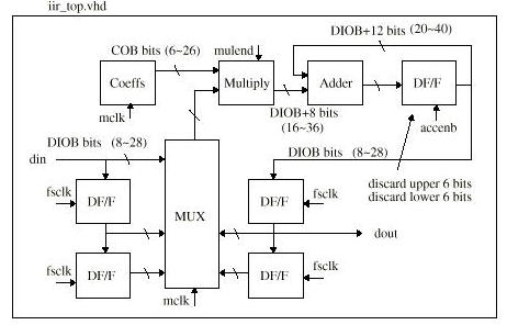
Block diagram is drawn like following. Input
data consists of DIOB bits (8 to 28) and
coefficients are COB bits(6 to 26). We have
just one multiplier with DIOBxCOB bits and
use it for all multiplications. Therefore
coefficients and data need to be multiplexed.
If you put 8 for "Bit
length of coeffs" on Digital Filter Analyzer, COB becomes 10. The
reason it has two margin bits is that sometimes the value of coefficients
exceeds 1.0 as real variables. Similarly, if you put 8 for "Bit length
of Input data" on the app, DIOB becomes 12. That's because sometimes
the value of internal signals exceeds 1.0 as real variables in case we
have multiple serial IIRs. .

Back
|