 FIR Filter Design Example FIR Filter Design Example
 Let's design an FIR filter putting parameters
like LPF, Tap Count=90, Sampling Frequency=1000,
Fc1=200, Fc2=250. Let's design an FIR filter putting parameters
like LPF, Tap Count=90, Sampling Frequency=1000,
Fc1=200, Fc2=250.

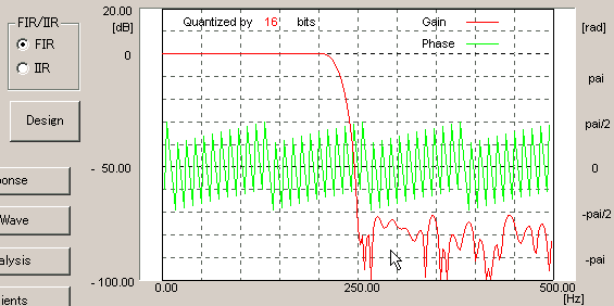
 Here is frequency response. The reduction
ratio of stop band has become 85dB. Here is frequency response. The reduction
ratio of stop band has become 85dB.

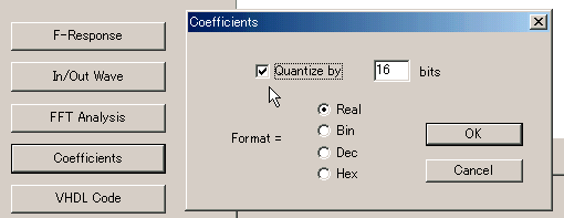
 In order to implement the filter into hardware,
you need to quantize coefficients by 16 bits. In order to implement the filter into hardware,
you need to quantize coefficients by 16 bits.

 The characteristics has changed a bit. The characteristics has changed a bit.

 Let's generate VHDL codes!! Please put 12
for bit length of input data. Let's generate VHDL codes!! Please put 12
for bit length of input data.

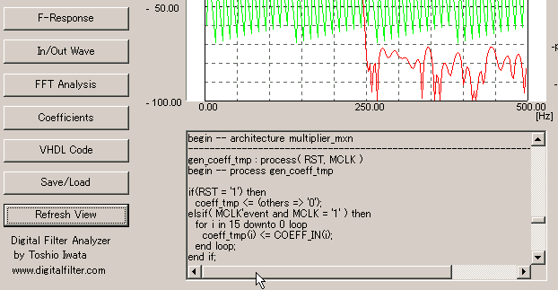
 The VHDL code has been listed up!! Let's
save it by clicking "Save/Load". The VHDL code has been listed up!! Let's
save it by clicking "Save/Load".

 Next Next
|


