 FIR Filter Design Example (Continued from
Previous Page) FIR Filter Design Example (Continued from
Previous Page)
 RTL simulation with "ModelSim"
(by ModelTech Inc.) RTL simulation with "ModelSim"
(by ModelTech Inc.)
 Environment and Test Scripts are located
on this page. Environment and Test Scripts are located
on this page.
 The designed filter: LPF, Tap Count=90, Sampling
Frequency=1000, Fc1=200, Fc2=250. The designed filter: LPF, Tap Count=90, Sampling
Frequency=1000, Fc1=200, Fc2=250.
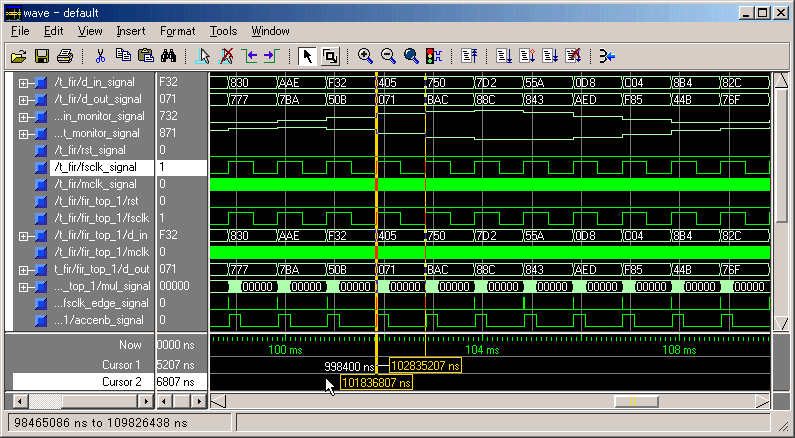
 Since the tap count is 90, there is some
delay (91 ms) before the output signal appears.
The frequency of input signal (D_IN) is 100Hz
in this case. So the output (D_OUT) remains
completely. (Simulator is ModelSim PE 5.7a) Since the tap count is 90, there is some
delay (91 ms) before the output signal appears.
The frequency of input signal (D_IN) is 100Hz
in this case. So the output (D_OUT) remains
completely. (Simulator is ModelSim PE 5.7a)

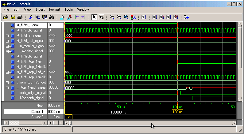
 FSCLK is 1kHz as a default setting. D_IN
and D_OUT consist of 12bits. (Simulator
is
ModelSim PE 5.7a) FSCLK is 1kHz as a default setting. D_IN
and D_OUT consist of 12bits. (Simulator
is
ModelSim PE 5.7a)

 Master Clock(MCLK) is 384xFSCLK or faster.
RST signal is high-enable and needs to stay
more than some MCLK cycles. (Simulator is
ModelSim PE 5.7a) Master Clock(MCLK) is 384xFSCLK or faster.
RST signal is high-enable and needs to stay
more than some MCLK cycles. (Simulator is
ModelSim PE 5.7a)

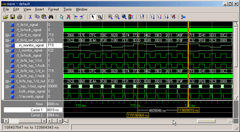
 If the input signal's frequency is 230Hz,
the output is somewhat filtered. (Simulator
is ModelSim PE 5.7a) If the input signal's frequency is 230Hz,
the output is somewhat filtered. (Simulator
is ModelSim PE 5.7a)

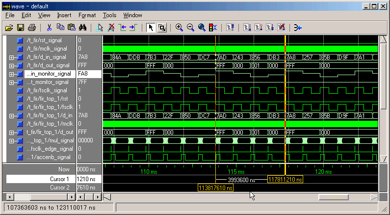
 If the input signal is 250Hz, the output
is removed almost completely. (Simulator
is ModelSim PE 5.7a) If the input signal is 250Hz, the output
is removed almost completely. (Simulator
is ModelSim PE 5.7a)

 Back Back
|


