 IIR Filter Design Example (Continued from
Previous Page) IIR Filter Design Example (Continued from
Previous Page)
 RTL simulation with "ModelSim"
(by ModelTech Inc.) RTL simulation with "ModelSim"
(by ModelTech Inc.)
 Environment and Test Scripts are located
on this page. Environment and Test Scripts are located
on this page.
 The designed filter: LPF, Number of IIRs=2,
Fc=200, Sampling Frequency=1000. The designed filter: LPF, Number of IIRs=2,
Fc=200, Sampling Frequency=1000.
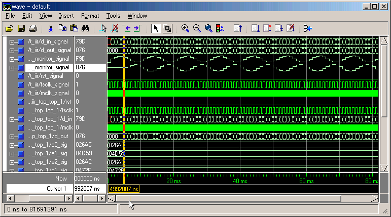
 The output signal appears immediately after
we have input signal. The frequency of input
signal (D_IN) is 100Hz in this case. So the
output (D_OUT) is not decreased. (Simulator
is ModelSim PE 5.7a) The output signal appears immediately after
we have input signal. The frequency of input
signal (D_IN) is 100Hz in this case. So the
output (D_OUT) is not decreased. (Simulator
is ModelSim PE 5.7a)

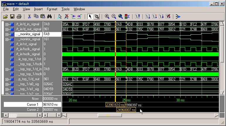
 FSCLK is 1kHz as a default setting. D_IN
and D_OUT consist of 12 bits. (Simulator
is ModelSim PE 5.7a) FSCLK is 1kHz as a default setting. D_IN
and D_OUT consist of 12 bits. (Simulator
is ModelSim PE 5.7a)

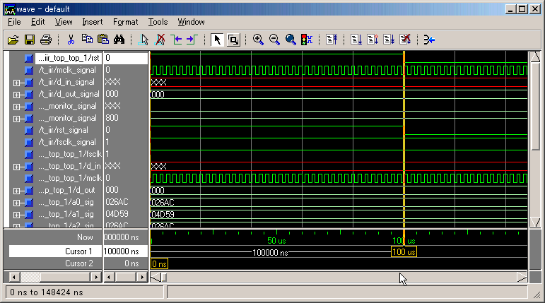
 RST signal is high-enable and needs to stay
more than some MCLK cycles. (Simulator
is
ModelSim PE 5.7a) RST signal is high-enable and needs to stay
more than some MCLK cycles. (Simulator
is
ModelSim PE 5.7a)

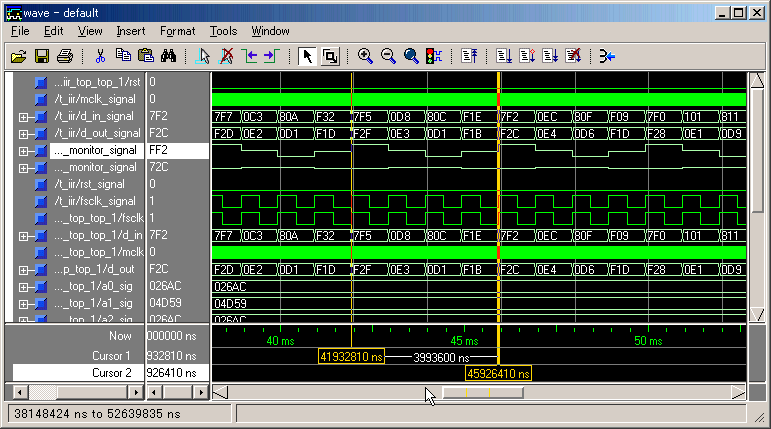
 If the input signal's frequency is 230Hz,
the output is somewhat filtered. (Simulator
is ModelSim PE 5.7a) If the input signal's frequency is 230Hz,
the output is somewhat filtered. (Simulator
is ModelSim PE 5.7a)

 If the input signal's frequency is 250Hz,
the output is decreased a lot. (Simulator
is ModelSim PE 5.7a) If the input signal's frequency is 250Hz,
the output is decreased a lot. (Simulator
is ModelSim PE 5.7a)

 Back Back
|


